Component diagram uml example
Table of Contents
Table of Contents
Have you ever struggled with creating a deployment diagram in Rational Rose? Are you unsure how to get started or what steps to take? Don’t worry! In this article, we will guide you through the process of creating a deployment diagram in Rational Rose, step by step.
Creating a deployment diagram in Rational Rose can be a daunting task, especially if you are new to the tool. It requires knowledge of the tool’s features, as well as an understanding of deployment diagram concepts. But fear not, we are here to help!
The first step in creating a deployment diagram in Rational Rose is to open the tool and create a new project. Once you have done that, select “Diagram” under the “Model Explorer.” From there, select “Deployment Diagram” and click “OK.” This will create a blank deployment diagram for you to work with.
To add components and nodes to your deployment diagram, simply drag and drop them from the “Model Explorer” onto the diagram. You can also use the tools in the “Deployment Diagram Toolbox” to add elements to your diagram. Once you have added all the necessary components and nodes, you can connect them using “Association” and “Dependency” connectors.
My Personal Experience with Rational Rose Deployment Diagram
When I first started using Rational Rose, I found it difficult to create a deployment diagram. I was unsure of the steps I needed to take and which components to add. However, with practice and guidance, I was able to create effective deployment diagrams that accurately depicted the system architecture.
Best Practices for Creating a Deployment Diagram in Rational Rose
When creating a deployment diagram in Rational Rose, it’s important to keep a few best practices in mind. Firstly, ensure that your diagram is clear and easy to understand. Use appropriate labels and organize your components and nodes logically. Also, ensure that your diagram accurately depicts the system architecture and includes all necessary components and nodes.
Labels and Definitions
When creating a deployment diagram, you need to ensure that all components and nodes are labeled appropriately. This includes providing clear definitions for each element. For example, if you are adding a database to your diagram, you need to label it “Database” and define its purpose in the system.
Layout and Organization
When creating a deployment diagram, it’s important to organize your components and nodes in a logical manner. This means grouping related elements together and laying them out in a way that makes sense. You can use the tools in Rational Rose to manipulate the layout of your diagram and ensure that it is easy to understand.
Question and Answer
How do I add components to my deployment diagram? To add components to your deployment diagram, drag and drop them from the “Model Explorer” onto the diagram. You can also use the tools in the “Deployment Diagram Toolbox” to add elements to your diagram.
Is it important to label my components and nodes? Yes, it is important to label your components and nodes with clear and descriptive labels. This makes your diagram easy to understand and helps others to interpret it correctly.
Can I manipulate the layout of my deployment diagram? Yes, you can use the tools in Rational Rose to manipulate the layout of your diagram and ensure that it is easy to understand. This includes adjusting the spacing, grouping elements together, and aligning components.
What is the purpose of a deployment diagram? The purpose of a deployment diagram is to show how the components and nodes of a system are deployed across different hardware and software environments.
Conclusion of How to Draw Deployment Diagram in Rational Rose
Creating a deployment diagram in Rational Rose can be a complex task, but with practice and guidance, it can be accomplished effectively. By following the steps outlined in this article, you will be able to create clear and accurate deployment diagrams that depict the system architecture effectively. Remember to label your components and nodes clearly, organize them logically, and ensure that your diagram accurately represents the system architecture.
Gallery
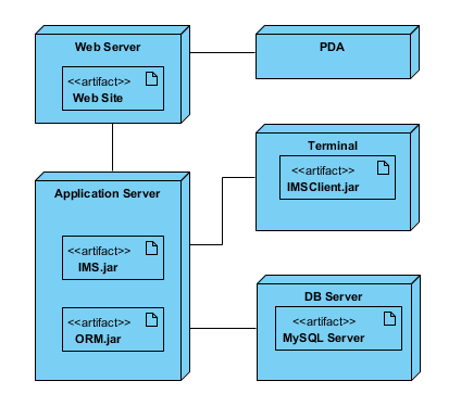
How To Draw A Deployment Diagram In UML?

Photo Credit by: bing.com / diagram deployment uml draw paradigm visual artifact
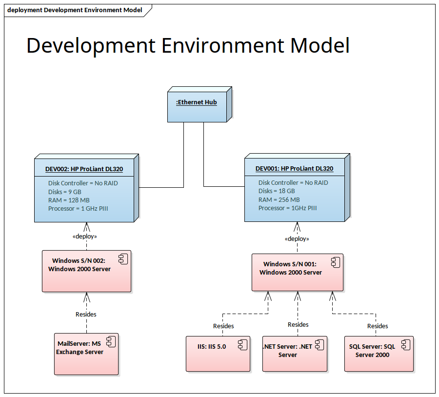
Component Diagram Uml Example - Diagram Media

Photo Credit by: bing.com / deployment uml 部署
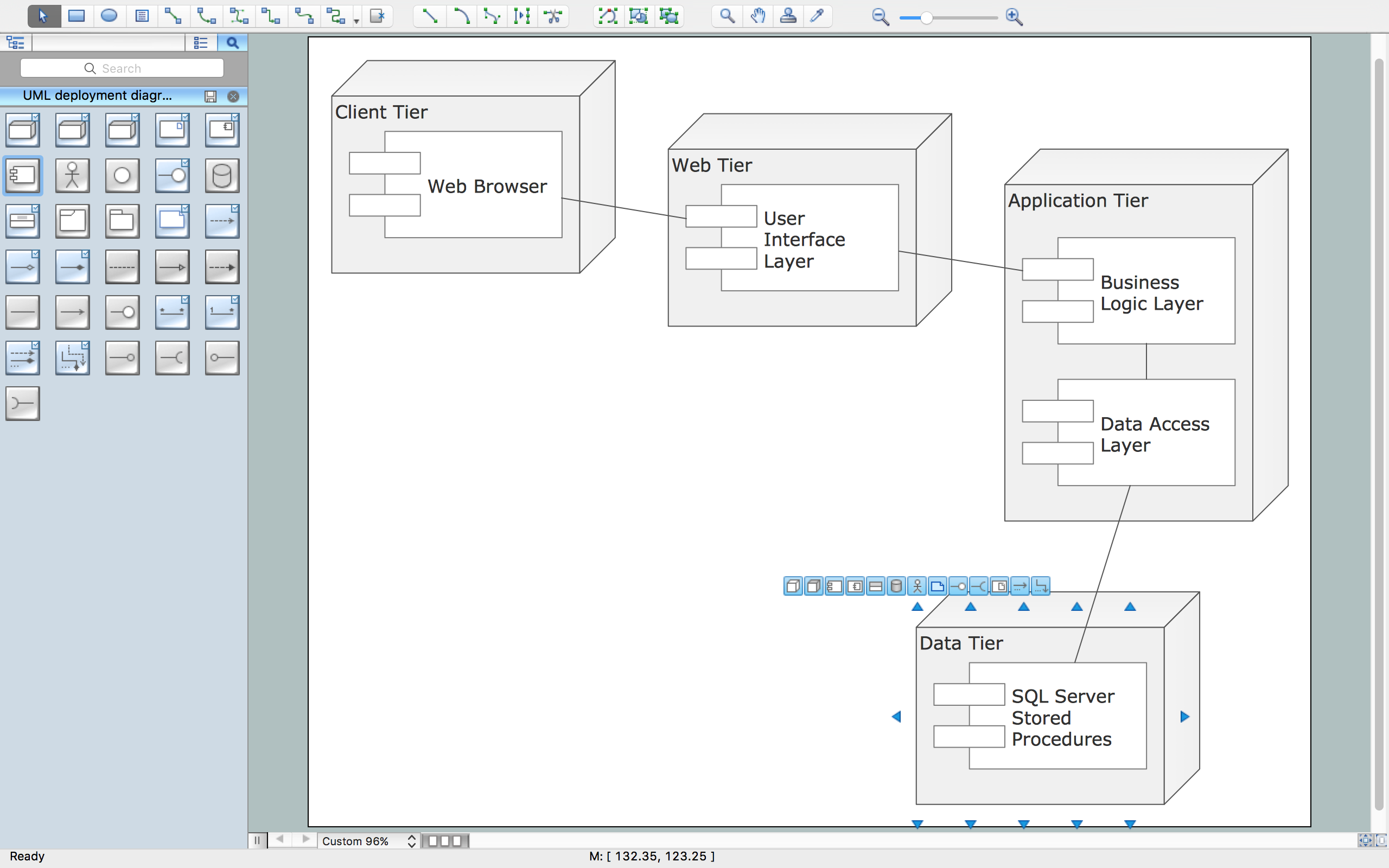
UML Deployment Diagram | Professional UML Drawing

Photo Credit by: bing.com / deployment diagram uml system example atm template diagrams software draw library systems engineering use elements notation conceptdraw guide resource
How To Draw Er Diagram Using Rational Rose | ERModelExample.com

Photo Credit by: bing.com / rational ermodelexample
How To Draw A Deployment Diagram In UML | Lucidchart
Photo Credit by: bing.com / diagram deployment draw uml tutorial complete


